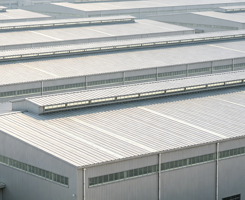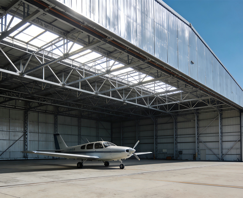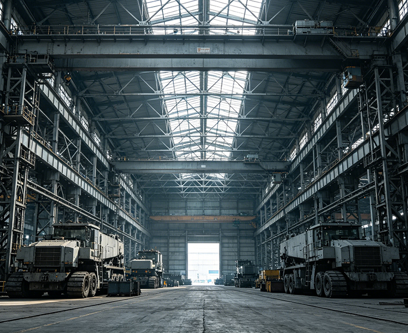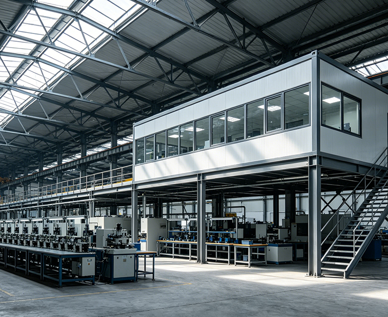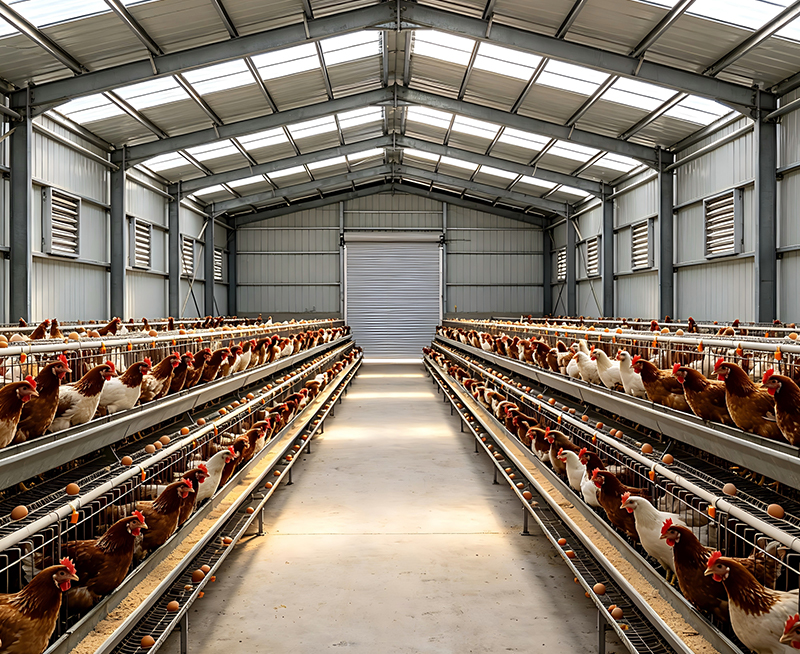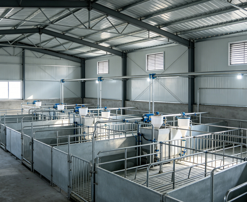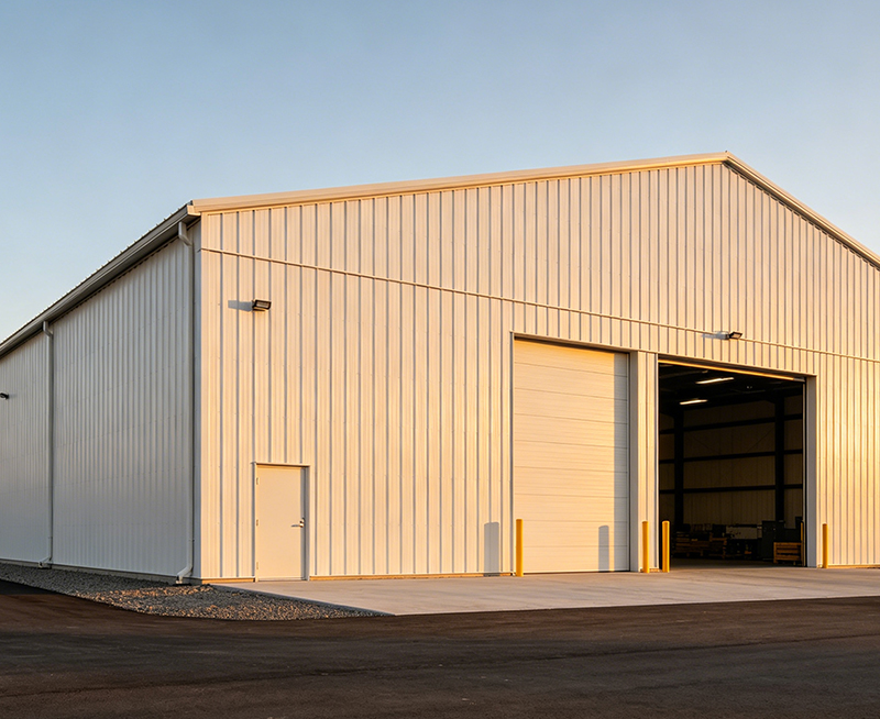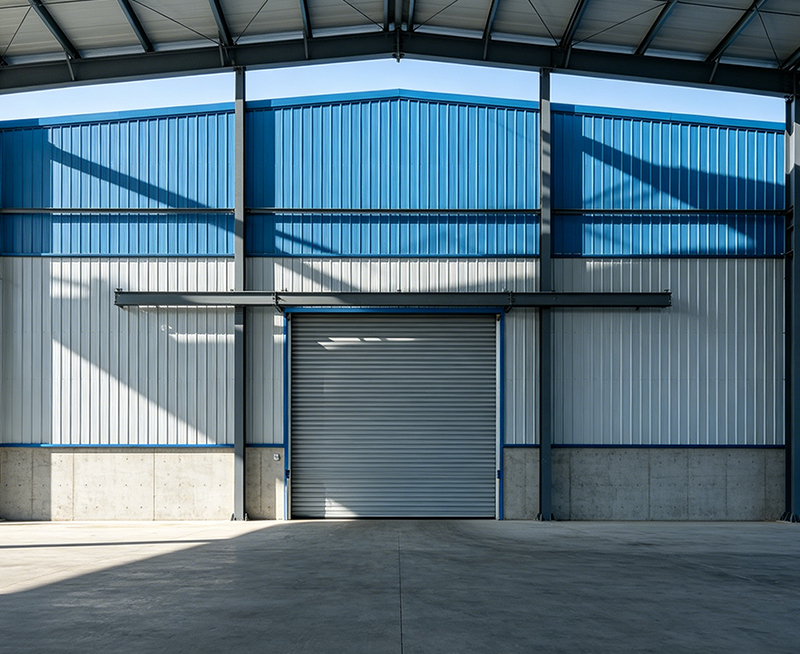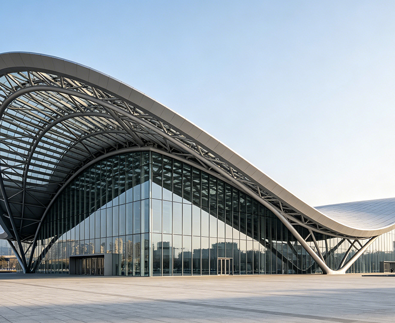


Our Steel Workshop Building Guide: Columns, Roofs, Walls and Floor Systems gives beginners and experienced project teams a practical route from site assessment to final inspection. We recommend beginning with the workshop’s operational requirements, then confirming the design loads, selecting the primary steel frame, coordinating roof and wall systems, engineering the floor slab, and completing fabrication, installation, and quality control in sequence. With Jin'an Group, the most reliable strategy is to combine a coordinated structural model, documented material certificates, factory inspection, accurate anchor-bolt setting, and site-based verification before commissioning the building.
!
A steel workshop is not simply a large enclosed shed. Its dimensions, crane loads, equipment arrangement, ventilation requirements, and production environment directly affect the structural system.
Before requesting a quotation from Jin'an Group, prepare the following project information:
This early data prevents common problems such as undersized portal frames, poorly positioned bracing, insufficient crane runway support, and floor slabs that cannot withstand forklift traffic.
For international projects, the design team may use AISC 360 and ASCE 7 in the United States, Eurocode 3 and EN 1991 in Europe, or the applicable national structural code. Jin'an Group should coordinate the selected code with the client, local engineer, and permitting authority before detailed design begins.
The columns transfer roof reactions, wind forces, crane loads, and sometimes mezzanine loads into the foundations. In most Workshop Steel Structure Buildings, the primary system consists of rigid portal frames, braced frames, or a combination of both.
Portal-frame columns are commonly fabricated as welded H-sections or tapered built-up members. They provide large clear spans and efficient material use.
Key design considerations include:
A tapered column can reduce steel weight where bending moments vary along the height. However, the taper, stiffener arrangement, and welded joint details must be accurately modeled and fabricated.
Braced bays use diagonal members, portal bracing, or vertical X-bracing to resist longitudinal wind and seismic actions. Bracing reduces frame drift and stabilizes the building during erection.
We normally recommend reserving braced bays away from major overhead doors and high-traffic areas. If a bracing line conflicts with a door, crane access route, or process layout, the engineer may need to introduce a moment frame or a transfer member.
The steel design cannot be separated from civil construction. A small anchor-bolt error can create major erection delays.
Before concrete placement, verify:
Surveying equipment should confirm the anchor layout before and after the concrete pour. Although CNC fabrication may achieve positioning accuracy to approximately 0.01 mm in controlled operations, field installation tolerances are governed by the project specification and applicable standards, not by machine accuracy alone.
The roof must control water, resist environmental loads, support maintenance activity, and protect the workshop interior. A low-cost roof that leaks or accumulates condensation can become more expensive than a properly engineered system.
Typical roof options include:
The selection depends on thermal performance, fire requirements, budget, climate, and internal humidity.
For industrial buildings with welding, washing, food processing, or high indoor humidity, condensation control is essential. The roof specification should address vapor barriers, thermal bridges, ridge ventilation, insulation continuity, and internal liner protection.
The structural engineer should verify:
Purlins are typically cold-formed Z or C sections connected between primary rafters. Their spacing must match the cladding manufacturer’s requirements and the design wind or snow pressure.
Roof drainage deserves special attention. We recommend checking gutter falls, outlet locations, flashing overlaps, sealant compatibility, and penetration details before installation. Every roof penetration should have a documented waterproofing detail rather than an improvised site solution.
The wall system determines weather resistance, insulation, appearance, and maintenance requirements. In a Steel Workshop Building Guide: Columns, Roofs, Walls and Floor Systems, the envelope should be treated as a coordinated assembly rather than a collection of separate panels.
| Wall system | Main advantage | Key limitation |
|---|---|---|
| Single-skin profiled sheet | Low initial cost and fast installation | Limited insulation and condensation control |
| Sandwich panel | Rapid installation and strong thermal performance | Panel joints and fire rating require careful specification |
| Masonry or concrete lower wall with steel upper wall | Impact resistance at floor level | Heavier foundations and slower construction |
| Insulated liner and external cladding | Flexible thermal and architectural design | More components and detailing |
For workshops using forklifts or moving heavy products, a concrete or masonry dado wall can protect the lower cladding from impact. Where a full-height metal wall is preferred, bollards and guardrails should be installed at vulnerable locations.
Wall performance depends on details at:
Use fasteners compatible with the coating system. Incorrect fasteners can cause galvanic corrosion or premature leakage. Sealants should be selected for ultraviolet exposure, temperature range, and movement capacity.
For fire-sensitive facilities, specify the correct core material and tested wall assembly. Relevant testing may include ASTM E84 for surface-burning characteristics, ASTM E119 for fire-resistance assemblies, or EN 13501-1 for European fire classification. The exact requirement depends on the local authority and the complete wall construction.
The floor is often the most heavily used part of a workshop. A visually attractive building can still fail operationally if the slab cracks, settles, dusts, or cannot support concentrated wheel loads.
We recommend listing every significant load, including:
A forklift rated for 5 tonnes does not apply only a 5-tonne evenly distributed load. Its axle load and small solid tires can create high local stresses. The slab thickness, reinforcement, subbase, and joint layout must be designed from the actual equipment data.
A dependable industrial floor typically includes:
The geotechnical report should establish allowable bearing pressure and settlement risk. Field density testing, such as ASTM D6938 where applicable, can verify compaction. Concrete compressive strength may be tested under ASTM C39, while slump can be checked under ASTM C143.
The slab design should also consider flatness and levelness. Warehousing, automated vehicles, and precision machinery may require tighter floor tolerances than general fabrication areas. Those requirements should be written into the specification before concrete placement.
Once the structural model is approved, fabrication should proceed through a controlled process rather than informal shop adjustments.
Jin'an Group’s production coordination should include:
For welded members, specify the appropriate inspection level. Common methods include:
A project may require 100% visual inspection and additional non-destructive testing on critical welds. Material certificates should identify the steel grade, yield strength, tensile strength, and applicable standard, such as ASTM A36, ASTM A572 Grade 50, EN 10025 S355, or the grade stated in the approved design.
For structural steelwork in Europe, EN 1090-1 execution class requirements should be reviewed. Welding quality management may also follow ISO 3834. Paint systems should identify surface preparation, dry-film thickness, primer type, intermediate coat, and topcoat. Galvanizing, where selected, can be specified and tested under ASTM A123 or ISO 1461.
Transport damage often occurs at corners, connection plates, and painted surfaces. Use:
Jin'an Group can support technical questions with a 24-hour response target when that service level is included in the commercial agreement. Clients should confirm response times, inspection scope, warranty terms, and document deliverables in writing.
A safe erection sequence reduces rework and prevents temporary instability.
High-strength bolts must be installed and tightened according to the approved method. Depending on the project specification, this may involve calibrated torque, turn-of-nut, or tension-control bolts. Do not rely on visual tightness alone.
Temporary bracing should remain in place until the permanent stability system is complete. Erection crews should use an approved lifting plan, exclusion zones, wind limits, fall protection, and daily toolbox talks.
To manage a Workshop Steel Structure Buildings project effectively, we recommend maintaining a shared document register containing:
A simple inspection and test plan should identify the hold points before fabrication, shipment, concrete placement, frame alignment, cladding closure, and final acceptance.
For large projects, a BIM model can help coordinate crane runways, roof penetrations, drainage, fire systems, ventilation ducts, and electrical cable trays before fabrication. This reduces clashes that would otherwise require field cutting or unauthorized welding.
Several recurring issues affect steel workshop construction.
Cause: Survey errors, template movement, or drawing revisions issued after foundation work.
Solution: Verify the bolt layout using a total station before concrete placement. If a discrepancy occurs, stop erection and obtain an engineered correction such as a revised base plate, approved shim arrangement, or foundation modification. Do not torch-cut or enlarge holes without written approval.
Cause: Incorrect flashing, insufficient side-lap sealant, damaged washers, or poorly detailed penetrations.
Solution: Perform a roof inspection before handover. Check every lap, fastener line, gutter outlet, ridge cap, and penetration. Replace damaged components instead of relying on additional surface sealant.
Cause: Inadequate subgrade preparation, underestimated wheel loads, poor joint detailing, or missing equipment foundations.
Solution: Compare the constructed floor with the approved geotechnical and structural design. Use core testing, level surveys, and load information to identify the cause. Repair methods may include joint reconstruction, slab replacement, resin injection, or a separate equipment foundation.
Cause: High internal humidity, cold metal surfaces, poor ventilation, or incomplete vapor control.
Solution: Improve insulation continuity, repair vapor barriers, add ridge or mechanical ventilation, and control process humidity. A dehumidifier alone may not solve a thermal-bridge problem.
Cause: Sling abrasion, welding spatter, impact, or poor storage.
Solution: Clean the affected area, prepare the substrate according to the coating manufacturer’s instructions, and apply an approved repair system. Record repaired locations in the inspection file.
In a representative Jin'an Group industrial workshop delivery, the project team coordinated a clear-span production area with overhead crane provisions, insulated roof and wall panels, and a heavy-duty concrete floor. The team divided the work into design approval, factory fabrication, pre-shipment inspection, foundation verification, staged erection, envelope installation, and commissioning.
The most important gains came from process control rather than a single material choice:
This approach illustrates why a complete Steel Workshop Building Guide: Columns, Roofs, Walls and Floor Systems must cover civil, structural, architectural, mechanical, and operational requirements together.
Before accepting the building, we suggest confirming the following:
A successful Steel Workshop Building Guide: Columns, Roofs, Walls and Floor Systems is ultimately a project-management system: define the operation, engineer the loads, coordinate every interface, inspect the steel, control erection, and verify the finished building. Jin'an Group can help clients organize these stages for Workshop Steel Structure Buildings, from portal-frame columns and crane-support details to insulated envelopes and industrial floor systems.
When the design basis, fabrication records, testing standards, erection sequence, and handover documents are controlled from the beginning, the workshop becomes safer, more durable, and easier to maintain. That is the practical value of following the complete Steel Workshop Building Guide: Columns, Roofs, Walls and Floor Systems rather than treating columns, roofs, walls, and floors as unrelated packages.

منتجات ذات صلة